|
 Introduction
Successful production of plastic components depends
on the mold, the machine and the processing conditions used. The
role of the mold becomes more important when we enter the arena
of molding precision components for demanding applications in engineering.
Crystalline plastics like polyacetals, have shrinkage is in two stages,
i.e. shrinkage in mold and post molding shrinkage. If tight tolerance
is to be maintained, one of the important aspects that is to be taken
care of is the mold design.
Let us look at some aspect of the mold design which
will help in molding precision components with relative ease, consistently.
|
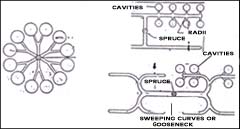
Cavity layout
The first aspect to be looked at is the cavity
lay-out in the mold. The basic objective for designing a cavity
layout is achieving equal cavity pressure in all the cavities
in a multicavity layout. Of course, for a single cavity, the
question of making a lay-out does not arise, but in case of
multicavities, a variety of aspects can be looked at in arriving
at a suitable cavity layout. A designer has to optimise by
adjusting the cavities’ location in such a way as to
minimise the flow path of the material and also reduce the
total area of the mold. The following is an interesting example
(See the above figure).
|
|
Runners
Runners are the feeding systems which feed
the cavity with the material. With this in mind, one should design
the runner system. Another governing factor is the melt viscosity.
For example, for feeding material for multicavities having a long
flow path, a lower melt viscosity material will be preferable to
the higher viscosity material. The runner lay out should transmit
pressure uniformly to all cavities. It should be enough to provide
enough flow of material with minimum pressure loss. Size and length
should be optimum to reduce the losses in form of runner and reduce
the amount of material available for rework.
The optimum runner cross section is a full round section or a trapezoidal
runner section which is relatively easier to machine. Hence the
depth of the trapezoid should be at a minimum the diameter of the
full round designed, which of course adds more material in the runner
which has to be recycled or rejected. The runners carry hot material
upto the cavity. The material which starts flowing first in the
path is cooled down due to the lower temperature of the mold. Hence
it is advisable to give a cold slug well at the end of the runner
path and the end of sub runner path, and design in such a way that
the cold material gets trapped in the slug well. This helps hot
material flood the cavity, thereby avoiding flowmarks, and aids
in increased packing of material in the cavity too.
|