The objective of flame retardant
thermoplastics is to increase the resistance
of a material to ignition and, once ignited,
to reduce the rate of flame spread. The product
does not become non-combustible, but the use
of a flame-retardant additive may prevent a
small fire from becoming a catastrophe.
The Burning Process of Plastics.
The combustion of plastics is a process comprising
many steps. A simplified schematic representation
of the various phenomena, which take place during
the combustion of plastics, is shown in Figure
1 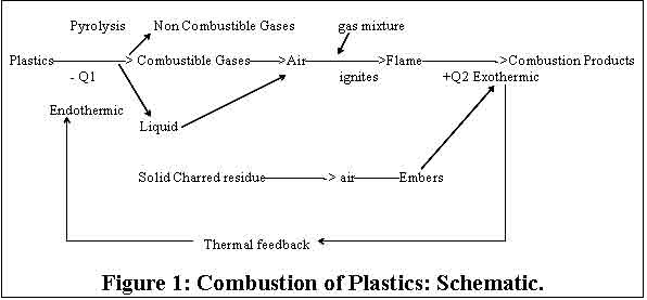
Three stages are necessary to initiate the actual
combustion process:
• Heating
• Decomposition
• Ignition
of the polymer
Heating
The solid plastic is heated by an external
source or by thermal feedback as shown in
figure 1. In this initial phase, thermoplastics
tend to soften or melt and start to flow.
Decomposition
Decomposition is an endothermic process in which
sufficient energy must be provided to overcome
the high binding energies of the bonds between
individual atoms (between 200 and 400kJ/mol.)
and to provide any necessary activation energy.
As the individual plastics differ in structure,
their decomposition temperature ranges vary
within certain limits. Table 1 gives the range
of decomposition temperature for some plastics
and for cellulose (a natural polymer).
Table 1: Range of Decomposition Temperature
of Some Thermoplastics
Thermoplastic
|
Decomposition
Temperature (Td Deg C)
|
Polyethylene
PE |
340-440 |
Polypropylene
PP |
320-400 |
Polystyrene
PS |
300 400
|
Polyvinyl
Chloride PVC |
200 300
|
PolytetrafluoroethylenePTFE
|
500 550
|
Polymethylmethacrylate
PMMA |
180 280
|
Polyacrylonitrile
PAN |
250 300
|
Polyamide
6 PA6 |
300 350
|
Cellulose
|
280 380
|
In most cases, decomposition
occurs via free radical chain reactions, initiated
by traces of oxygen or other oxidizing impurities,
which are trapped in all plastics during manufacture.
The oxidative degradation of polymers usually
proceeds via the formation of hydroperoxide
groups whose decomposition leads to highly reactive
species such as H & OH radicals and thus
to chain branching. These radicals are responsible
for flame spread in the combustion process.
Ignition
The flammable gases formed by pyrolysis,
mix with atmospheric oxygen, and reach the lower
ignition limit and are either ignited by an
external flame or, if the temperature is sufficiently
high, self-ignite. The flash ignition temperature
(FIT) and self-ignition temperature (SIT) are
given in Table 2.
Table 2: FIT and SIT of Some Thermoplastics.
| Polymer
|
FIT
Deg C |
SIT
Deg C |
| PE |
340
|
350
|
PP
|
320
|
350
|
PS
|
350
|
490
|
PVC
|
390
|
450
|
PTFE
|
560
|
580
|
ABS
|
390
|
480
|
PMMA
|
300
|
430
|
PAN
|
480
|
560
|
PA
6 |
420
|
450
|
PA
66 |
390
|
530
|
PU
Foam |
310
|
415
|
Cotton
|
210
|
400
|
Ignition depends on numerous
variables such as oxygen availability, temperature,
physical and chemical properties of polymer.
The reaction of the combustible gases with oxygen
is exothermic and if sufficient energy is available,
overrides the endothermic pyrolytic reaction
and initiates flame spread.
Flame Spread
The exothermic combustion reaction
reinforces pyrolysis of the polymer by thermal
feedback and fuels the flame at an increasing
level.
Another factor, which determines the extent
of flame spread, is the heat of combustion of
the polymer. The heat of combustion of various
polymers are compared with those of cotton and
cellulose in Table 3.
There is no correlation between the heat of
combustion and combustibility of a material.
An example of this is extremely flammable celluloid,
which has a heat of combustion of only 17,500
kJ/Kg.
Concurrent with the extremely
rapid gas phase reactions, various slower oxygen-
dependant reactions also take place. These give
rise to soot and carbon-like residues and take
place partly in a condensed phase with glow
or incandescence.
Table 3: Heat of combustion of various
plastics and natural polymers
Polymer
|
Heat
of Combustion, kJ/Kg |
PE
|
46,000
|
PP
|
46,000
|
PIB
|
47,000
|
PS
|
42,000
|
ABS
|
36,000
|
PVC
|
20,000
|
PMMA
|
26,000
|
PA
6 |
32,000
|
Polyester
resin |
18,000
|
Natural
rubber |
45,000
|
Cotton
|
17,000
|
Cellulose
|
17,000
|
Celluloid
|
17,000
|
Burning Behavior of Polyolefins
Polyolefins burn hesitatingly
at first with a small bright blue flame (PE
LD and PE HD) and subsequently, with a bright
yellow flame, which continues to burn after
removal of the ignition source. The fire gases
and smoke vapors smell of wax and paraffin.
This odor is pungent in the case of PP. After
the flame is extinguished a smell of dead candle
remains. In the absence of oxygen, PE starts
to degrade thermally at about 300 Deg C. In
the presence of Oxygen, thermal degradation,
thermal degradation sets in at 150 Deg c with
the color changing from white through brown
to black. PP undergoes thermal degradation more
easily than PE particularly when oxygen is present.
Flame Retardant Polyolefins
The primary additives used
to accomplish the objective of imparting flame
retardancy to Polyolefins are halogens and phosphorus
containing organic compounds. Antimony oxide
is generally required as a synergist for halogen
compounds. Inorganic compounds containing high
concentration of water of hydration such as
alumina trihydrate and magnesium hydroxide are
also used. The type of flame retardant and quantity
needed for polyolefin applications are largely
governed by cost/performance ratio.
Manufacture of Flame Retardant Polyolefins
World over flame retardant
polypropylene compounds are finding increasing
use in injection molding and fiber applications.
In this application note, we would focus only
on FR/PP compounds for injection molding applications.
FR/PP compounds are best made on a twin screw
compounding extruder having a l/d of 40:1 and
equipped with side feeder arrangement for dosing
FR additives. Gravimetric dosing units are needed
for accurate metering of FR and other additives
in to the polymer matrix.
Tailor-made formulations can be prepared depending
on end user specifications.
For injection molding application, a typical
temperature profile in the injection-molding
machine is
Zone 1or hopper
end |
Zone 2 |
Zone 3 |
Zone 4 |
Nozzle |
Melt
Temperature |
165 |
200 |
210 |
215 |
225 |
220 |
This temperature profile is
subject to change depending on the flow length/thickness
ratio of the product and capacity of the machine.
FR additives affect the metal surface in the
hopper, barrel and screw of the compounding
and molding machines. Hence it is recommended
to purge the machines with high flow LLDPE/LDPE
or with any commercially available purge resins.
Testing of Flame Retardant Plastics
Flame retardant Polyolefins
are frequently designed to meet specific flammability
tests. The laboratory tests used most frequently
for thermoplastics are described here.
Ease of Ignition: Oxygen Index
Ease of ignition may be defined as
the facility with which a material or its pyrolysis
products can be ignited under given conditions
of temperature and oxygen concentration. This
characteristic provides a measure of fire hazard.
ASTM D 2863-77 describes the test protocol for
measuring oxygen index.
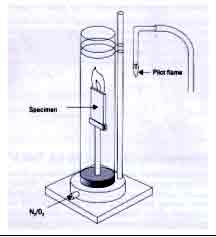
The oxygen index test employs
a vertical glass tube 60 cm high and 8.4 cm
in diameter, in which a clamp at its bottom
end holds a rod or strip specimen vertically.
A mixture of oxygen and nitrogen is metered
into the bottom of the tube, passing through
a bed of glass beads at the bottom to smoothen
the flow of gas, providing a specific environment
for the sample. The sample is then ignited at
its upper end with a hydrogen flame, which is
then withdrawn. The sample then burns like a
candle from the top down. (Figure 2). The atmosphere
that permits steady burning is then determined.
The oxygen index or the limiting
oxygen index, is the minimum percent of oxygen
in an oxygen-nitrogen mixture that will just
sustain burning for 2 inches or 3 minutes, whichever
comes first.
2. Flammability Testing for Electrical
and Electronic Materials UL94
The most widely accepted flammability
performance standards for plastic materials
are UL (94) ratings designed by Underwriter's
Laboratories Inc., USA . These ratings are intended
to provide an indication of a material's ability
to extinguish a flame once ignited. Several
ratings can be applied based on the rate of
burning, time to extinguish ability to resist
dripping and whether or not drips are burning.
Each material tested may receive
several ratings based on color and/or thickness.
When specifying a material for an application,
the UL rating should be applicable for the thickness
used in the wall section in the plastic part.
The UL rating is "always"
reported with the thickness. UL rating
reported without specifying thickness is insufficient
and can be misleading.
The UL-94 has four separate sections containing
different test methodologies and these are described
hereafter: -
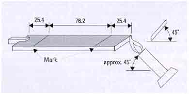
UL 94 HB Horizontal
Burning Test Procedure
In general, HB materials are not recommended
for electrical properties except for mechanical
and/or decorative purposes. Sometimes misunderstood:
materials that are not meant to be FR materials)
do not automatically meet HB requirements. UL
94 HB is, although the least severe of flammability
classification has to be checked by testing
Test Protocol
The test places a sample 127mm
(5.0 inches) long and 12.7mm (0.5 inches) wide
in a horizontal position over a standard Bunsen
burner. The test measures burn rate in mm/min
or inches/min.
A sample, should not have a burn rate exceeding
76mm/min for thickness less than 3mm
A schematic of the test protocol is shown in
Figure 3.
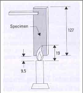
• UL 94 V0, V1 & V2 Vertical
Testing Procedure
The vertical tests (Figure
4) take the same specimens as are used for the
HB test. Burning times, glowing times, when
dripping occurs and whether or not the cotton
beneath ignites are all noted. Framing drips,
widely recognized as a main source for the spread
of fire or flames, distinguish V1 from V2
Test Protocol
A sample 127mm (5.0 inches)
long and 12.7mm (0.5 inches) wide is suspended
vertically over a Bunsen burner flame. The thickness
generally adopted is 0.8mm, 1.6mm or 3.2mm.
The distance between the test specimen and cotton
beneath is 300mm or 12 inches. A 20mm methane
flame is applied for two, ten second ignitions.
Different classifications are accorded depending
on the burning characteristics of the material.
• A V0 material
may not burn for over 10 seconds after the removal
of the flame. It may also not have flaming drips
which can ignite the cotton placed beneath the
test specimen
• A material rated V1 may burn for
a period not exceeding 30 seconds and not have
any flaming drips
• A material rated V2 may also not
burn over 30 seconds, but may have following
drips which ignite the cotton
• A material which does not pass
any of these categories is rated as " Failure
"
UL94 5V, 5VB & 5VA Ratings
These are high performance ratings and are
not considered here in this paper
Summary
A summary of the UL 94 rating categories is
provided below: -
#
|
Criteria
Conditions time in sec |
94V0
|
94V1
|
94V2
|
1
|
After flame
time for each individual specimen |
<
10 |
<
30 |
<
30 |
2
|
Cotton ignited
by flaming drips or particles |
No
|
No
|
Yes
|
• Flame
Spread.
Flame spread, or the rate of travel
of a flame front under given conditions of burning,
is a measure of fire hazard. The spreads of
flame along the surface of a material can transmit
fire to more flammable materials in the vicinity.
The Underwriters Laboratories
25 ft.tunnel test developed by Steiner is perhaps
the most widely accepted test for surface flame
spread. The test requires a specimen 25ft long
and 20 in. wide, mounted face down to form the
roof of a 25 ft-long tunnel 17 ½ in.
wide and 12 in. high. The fire source, two gas
burners 1 ft from the fire end of the sample
of select grade red oak flooring would spread
flame 19 ½ ft from the end of the igniting
fire in 5 ½ Minutes +/- 15 sec. The end of the igniting
fire is considered as being 4 ½ Ft from the burners, this flame
length being due to an average air velocity
of 240+/- 5 min. Flame spread classification
is determined on a scale on which asbestos
cement board is zero and select-grade red oak
flooring is 100.
• Smoke Measurements.
Smoke or smoke density is defined
as the degree of light obscuration produced
from the burning of a material under a given
set of combustion conditions. This characteristic
provides a measure of fire hazard in that occupants
have a better chance of escaping from a burning
structure if they can see their way. ASTM E662-83
Specific Optical Density of Smoke Generated
by Solid Materials is used to determine the
smoke density characteristics of a material
under controlled laboratory conditions.
The smoke density chamber test
is used to determine the specific optical density
of smoke generated within a closed chamber due
to non-flaming pyrolytic decomposition and/or
flaming combustion. The non-flaming mode employs
an electrically heated radiant energy heat source
with an irradiance level of 2.5W/cm^2. For the
flaming mode, a six tube burner, fuelled with
a mixture of propane and air, is used in combination
with the radiant heat to apply a row of equidistant
flamelets across the lower edge of the specimen
and into the sample trough.
Light transmission measurements
are used to calculate the specific optical density,
which is derived from a geometrical factor associated
with the dimensions of the test chamber and
specimen, and the measured optical density,
a measurement characteristic of the concentration
of the smoke. The photometric scale used to
measure the smoke generated in this test is
similar to the optical density scale for human
vision.
(By Product
Application & Research Centre, Reliance
Industries Limited, Mumbai)
|