 |
 Compounding of Polypropylene Compounding of Polypropylene |
 |
|
| |
When particularly good dispersion is required, a better option for incorporating these additives is to produce an additive concentrate. To obtain the necessary dispersion in the final product, the concentrate is produced utilizing a fluxed melt mixer such as a Banbury prior to extrusion. The extruded concentrate may then be blended with the polymer matrix during a final compounding stage or may be added during the final moulding or extrusion step. Colour concentrates are a well known example, but lubricants. UV/light stabilizers may also be incorporated in this manner.
• High Add Levels
• Single screw extrusion
|
The addition of higher-add-levels of fillers and reinforcements may be done on a single screw or a twin-screw extruder. The choice is determined by the type of filler/reinforcement. In general, the single screw use is limited to low-aspect-ratio additives such as Ca CO3 and talc.
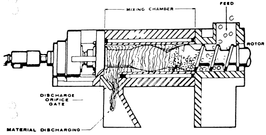
The production of CaCO3 filled and talc filled materials may be accomplished using only a dry-solid mixer and a two-stage vented extruder. An Auger-type hopper stuffer assists feeding. As the filler level increases, melt fluxing mixers, such as Farrel Continuous Mixer (Figures 2) may be used to optimize mixing and distribution. The Farrel Continuous Mixer is a counter rotating, non-intermeshing twin-rotor mixer. It can be divided into 3 zones: (a) Feed zone (b) Mixing zone (c) Discharge zone. The feed zone of the mixer is designed to opimize ingestion and delivery of feed m material (s) into the mixing zone. Upon entering the mixing zone, the feed material is melted and then continuously fluxed, pumped, backmixed and it exits through the discharge zone. The maximum achievable loading will depend, to some extent, on the melt viscosity of the polymer, but primarily on the type of filler. For example, specialized Ca CO3 concentrates have been produced with filler levels upto 80%, while it is difficult to reach a 50% loading with mica.
At high filler loadings, intensive mixing may not be necessary, as long as the filler is uniformly distributed. Over-mixing can cause separation. In general, both batch (Banbury) and continuous(FCM type) mixers are suitable.
metered feeding is necessary for all high filler-level systems. Fillers such as CaCO3 are liable to bridge in the hopper. In addition, there is a potential for separation and build-up of the filler on vertical metal surfaces. The critical design features of the feeders are the agitator and the feed screw and their relationship with each other. The agitator should sweep the hopper walls as closely as possible to prevent filler build-up. The hopper should be equipped with a level control feeder.
|
SECTIONAL VIEW OF TYPICAL FCM IN OPERATION |
|
The compoudning extruder should have relatively shallow flights. A compression ratio of 2.5:1 is preferred and no additional mixing devices are generally required.
Mineral fillers tend to be hygroscopic. Therefore, a vacuum vent is utilized during the extrusion step. When a cold-cut pelletizing system is used, the emerging strands from the die face is taken into water bath and taken out quickly, taking care to ensure integrity of the strands. A blower assists water removal from the strands prior to chopping.
Reciprocating Extruders
In these types of machines, both rotational and reciprocating action of the screw occur simultaneously and are continuous. These machines are specifically designed to enhance mixing performance and are ususally referred to as Ko-Kneaders.
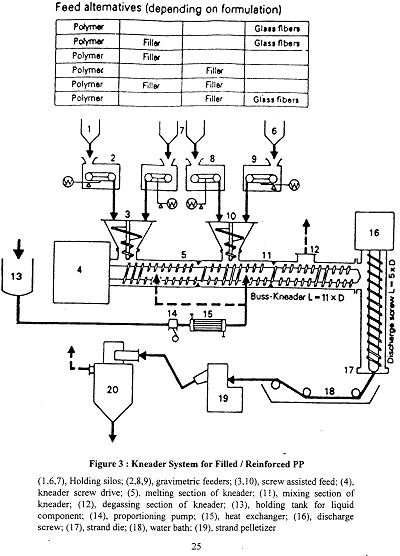
A schematic sketch of a Ko-Kneader is shown in Figure (3). The Kneader is a single screw extruder with interrupted screw flights and stationary pins or teeth in the barrel. The screw flights can be continuous in the feed section and vent section to improve forward conveying. In this section, no pins are located in the barrel. The mixing sectionof the screw is typically double-fighted with a small helix angle of 13 degree. The interruptions in the screw flights leave flight segments that look like vanes. There are three rows of pins or teetha along the length of the barrel. The barrel has a clamshell design, which facilitates cleaning of the barrel. Modern kneaders have a typical L/D ratio of about 11.
PP can be compounded with CaCO3, talc and glassfibres on Ko-Kneaders,
Twin screw extruders
The compounding of fillers, reinforcements, flame retardants (solids/liquids) can be achieved with a twin-screw extruder. Twin-screw extruders are designed to allow flexibility in the method of component intruduction, in addition to the ability to change screw configuration. The extruder comes configures with multiple feed ports, allowing the polymer components to be added as specified by the compounder. For example, the resin is generally added at the beginning of the extruder to ensure melting, mixing and uniformity of melt temperature, while fillers/reinforcing agents or liquid additives are added further downstream.
Twin-screw extruders make use of starve feeding systems as opposed to flood feeding system utilized with single-screw extruders. Side feeders for filler addition are also employed. Venting, pelletizing and downstream handling requirements are all similar for systems described in section 3.2-1. |
Feed alternatives (depending on formulation) |
|
Flame Retardant PP
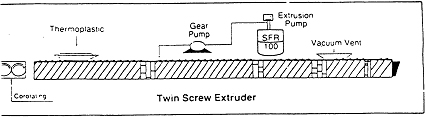
A schematic sketch of a typical twin-screw set up for introducing liquid flame retardant into PP is shown in Figure (4). The extruder set up requires two feeding ports, one for PP and one injection port for additive located downstream. The first section of the extruder creates a melt pool before the liquid is injected. The viscosities of the polymer melt and liquid are matched near the injection port and then the mass is allowed to homogenize in the latter part of the extruder. The factors which govern the quality of the final product are the temperature profile in the extruder, screw design and extruder geometry.
Filled PP
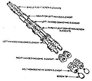
Filled PP grades can be compounded with twin screw extruders. Dispersion requirements for talc and CaCO3 vary according to the final product application. The primary objectives are uniform incorporation and mixing. A schematic diagram of mixing elements which make up a configurations shown in Figure (5).
Fillers are added downstream t a melt to isolate their abrasive effects. A melt seal is formed upsteam where large pitch screws are used. The downstream section is configured for low shear mixing for low performance applications. Applications requiring high degree of dispersion are compounded using a high shear intensive mixing section.
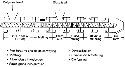
Glass Fibre Filled PP
Compounding technique for incorporating glass fibre into PP requires isolation of high and low shear sections along the screw length. Chopped fibres or continuous rovings can be used. The design of the screw determines the final firbre length in PP. PP in powder/pellet form is metered into the feed zone with stabilizers and lubricants. The additives can be preblended or metered individually. A relatively high shear plasticizing and mixing section is used to generate a homogeneous melt. Fibres are introduced into the melt via second feed opening located downstream (figure 6.) Metering equipment is required for chopped strands. Continuous rovings are continuously unwound from the core, drawn in by the turning screw. One inside the barrel, the continuous rovings are chopped to length by the kneading elements located downstream of the feed opening. A less intensive mixing section is needed for chopped fibre, since the fibres have only to be wetted out and dispersed. Degassing and die extrusion follows the compounding step.
Table (14) shows the effect of compounding technique on physical properties of glass fibre filled PP product. It is, therefore, important to select the correct compounding machine to obtain reinforced products with desired mechanical properties.
|
Table - 14
Effects of Compounding Technique on 20% glass reinforced-PP |
Property |
Standard twin screw |
Intensive twin screw |
Fluxed melt mixer |
Melt flow rate, condition L.g/10 min. |
4 |
5 |
9 |
Tensile strength (yield) MPa
|
79 |
70 |
49 |
Yield elongation, % |
2.8 |
3.1 |
5.1 |
Flexural modulus (1% secant), MPa |
4071 |
3726 |
26.22 |
Heat deflection temp. (264 psi), deg. C. |
134 |
134 |
104 |
Fibre length (average), um |
550 |
550 |
300 |
|
Twin screw-extruder for introducing liquid FR into PP
|
|
Twin screw Extruder
Continuous Twin Screw |
|
Typical configuration for glass fibre incorporation into PP |
 |
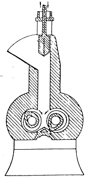
Schematic view of a Banbury Type Internal Mixer |
 |
(Contributed by Reliance Industries Limited-
Product Application & Research Center) |
|
| |
| |
|
|
|
| |
|